The 7 most common concrete defects and how to spot them early
In industrial plants, concrete carries a great deal – foundations, columns, chimneys and silos. Like any building material, it ages and can develop defects that reduce its load-bearing capacity and service life. This article presents the seven most common types of concrete damage: mechanical cracking and spalling, chemical attack such as carbonation, chlorides and sulphates, frost damage and biological growth. For each one you will learn how to recognise it, which testing methods detect it and what a drone inspection contributes.
Concrete is the basis of many industrial structures – from columns and foundations to storage tanks and silos. In heavy industry and power generation, these structures are exposed to high loads. Detecting damage early increases safety and avoids unplanned outages.
Christian Engelke
1. Cracking caused by mechanical loads
Cracks caused by tensile and shear forces: flexural, shear and settlement cracks Mechanical loads are one of the most common causes of cracks in concrete. Flexural cracks run perpendicular to the member axis, shear cracks diagonally at roughly 45°. They form when the tensile strength is exceeded and are often the first sign of structural weakness. As water and pollutants penetrate through cracks, the risk of corrosion of the reinforcement increases.
Formation
Mechanism
Tensile stresses exceed the tensile strength of the concrete – which is only around 10% of its compressive strength.
Microcracks develop into visible cracks.
Types of crack
Flexural cracks
Start on the tension side and run perpendicular to the axis of the member.
Typical on the underside of beams and at midspan of slabs.
Shear cracks
Diagonal, at around 45° to the axis of the member.
Typical near supports and load application points.
Torsional cracks
Spiral around the member.
Settlement cracks
Caused by uneven settlement, often diagonal in walls.
Assessment
Crack widths
Permissible crack widths depend on the exposure class and the requirements for the member (Eurocode 2 with national annex).
The assessment is carried out by structural engineers or expert assessors.
Measurement
The crack width can be estimated from the close-up images; exact measurements are taken only where necessary.
Documentation of width, length and course; repeated measurements show whether a crack is growing.
Consequences and prevention
Consequences
Corrosion of the reinforcement, frost damage, chemical attack, in extreme cases loss of load-bearing capacity.
Prevention
Adequate reinforcement and concrete cover, sensibly placed joints.
Careful compaction and curing.
Detectable by drone
Visual inspection
Position and course of cracks recorded across the whole surface and located in the 3D point cloud.
Crack widths can be estimated from the close-up images; exact measurements follow only where necessary, at the points marked in the inspection report.
2. Spalling on edges and surfaces
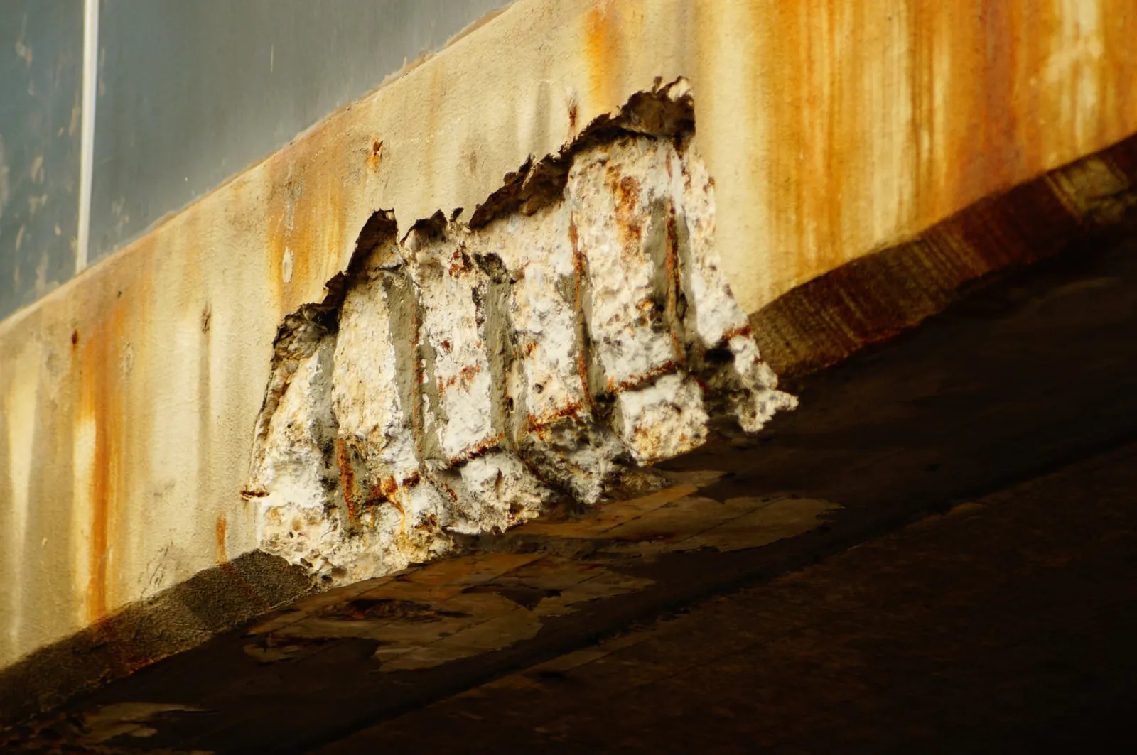
Surface damage caused by freeze–thaw cycles and mechanical impact Spalling is caused by mechanical stress, corroding reinforcement or freeze–thaw cycles and often exposes the reinforcement. Areas with traffic or strong swings between heat and cold are particularly affected. Spalling should be repaired in good time so that the reinforcement does not corrode further.
Appearance
Forms
Spalling at corners and edges.
Delamination of the concrete cover over larger areas.
Exposed aggregate or reinforcement.
Causes
Mechanical
Impact, falling objects, overloading.
Abrasion and erosion from traffic or flowing water.
Chemical and physical
Corroding reinforcement: rust takes up more space than steel and bursts off the concrete cover.
Freeze–thaw cycles, fire, thermal shock.
Construction
Insufficient concrete cover.
Poor compaction (honeycombing), faulty curing.
Inspection
By drone
Visual inspection and damage mapping.
Position and extent of spalling, located in the 3D point cloud.
Targeted on the component / laboratory
Hammer testing for voids, concrete cover, carbonation depth, chloride content – at the points marked in the inspection report.
Repair
Immediate measures
Cordon off the area, remove loose pieces.
Permanent
Remove damaged concrete, de-rust and protect the reinforcement, reprofile the section.
Surface protection, edge and impact protection.
Detectable by drone
Visual inspection
Spalling and exposed reinforcement are clearly visible.
Voids without visible spalling are revealed only by hammer testing or, under suitable conditions, by thermography.
3. Carbonation: loss of corrosion protection
Chemical reaction with CO₂ – a threat to the reinforcement During carbonation, CO₂ from the air reacts with the concrete and lowers its pH value. As a result, the natural corrosion protection of the reinforcement is lost. A phenolphthalein test makes visible how deep the carbonation reaches.
Process
Chemical reaction
Ca(OH)₂ + CO₂ → CaCO₃ + H₂O
The pH value falls from around 13 to below 9.
Progress
The front moves from the outside inwards.
The depth increases roughly with the square root of time: x = k · √t (x = carbonation depth, k = carbonation coefficient, t = time).
Strongest at around 50–70% relative humidity.
Consequences for the reinforcement
Depassivation
Below a pH of around 9, the protective passive layer on the steel is lost.
Corrosion
With moisture and oxygen, the steel corrodes, usually over a wide area.
Rust expansion leads to cracks along the reinforcement and to spalling.
Influencing factors
Concrete
Water–cement ratio, type of cement, compaction, curing.
Thickness of the concrete cover.
Environment
CO₂ content, humidity, heat.
Inside or outside, exposed to rain or sheltered.
Measurement
Phenolphthalein test
On a fresh fracture or core surface.
Red-violet: not carbonated; colourless: carbonated (colour change at around pH 9).
Comparison
Carbonation depth compared with the measured concrete cover.
Protection and repair
Prevention
Dense concrete with a low water–cement ratio, adequate concrete cover.
Coatings that slow the ingress of CO₂.
Repair
Remove carbonated concrete, protect the reinforcement, reprofile.
Alternatively, electrochemical realkalisation.
Detectable by drone
Visual inspection
Carbonation itself is not visible.
Its consequences are visible: rust stains, cracks along the reinforcement, spalling. The carbonation depth is measured specifically at the marked points.
4. Chloride attack and pitting corrosion
Aggressive conditions where de-icing salt is used and in coastal environments In car parks, on bridges, in plants near the coast or where process media contain chlorides, chlorides penetrate the concrete and cause pitting corrosion of the reinforcement. It is highly localised and can severely weaken the steel cross-section even though little is visible on the outside. Exposed structures should therefore be inspected regularly.
Sources and ingress
Sources
De-icing salt, seawater and spray.
Chloride-containing process media and industrial atmospheres.
In the past, also chloride-containing admixtures.
Ingress routes
Capillary suction and diffusion.
Cracks and defects.
Corrosion mechanism
Pitting
Above a critical chloride content, the passive layer is destroyed locally.
Deep pits form with a severe loss of cross-section.
Electrochemistry
Anode: Fe → Fe²⁺ + 2e⁻
Cathode: ½O₂ + H₂O + 2e⁻ → 2OH⁻
Damage patterns
Outside
Rust stains, cracks along the reinforcement, spalling.
Inside
Loss of cross-section and bond defects – often further advanced than is visible from the outside.
Testing
Chloride content
Drill dust samples at several depths produce a chloride profile.
Corrosion
Half-cell potential mapping, cover measurement.
Prevention and repair
Prevention
Dense concrete with a low w/c ratio, adequate concrete cover.
Surface protection and good drainage.
Repair
Remove and replace chloride-contaminated concrete.
Electrochemical chloride extraction or cathodic corrosion protection.
Detectable by drone
Visual inspection
Rust stains, cracks and spalling are captured and located.
Only a sample can determine the chloride content.
5. Freeze–thaw damage
Repeated freeze–thaw cycles loosen the concrete structure Water penetrates the pores of the concrete, freezes and damages the microstructure – up to the point of spalling. De-icing salts intensify this process. Regular checks are advisable for free-standing structures and unprotected areas of a plant.
Mechanism
Physics
Water expands by around 9% when it freezes.
In water-saturated concrete, hydraulic pressure and ice lenses develop.
De-icing salt
Increases water saturation and creates additional stresses in the surface zone (freeze–thaw attack with de-icing salt).
Damage patterns
Surface
Scaling and sanding, exposed aggregate.
Shell-like spalling, edge damage.
Structure
Map cracking and microcracks, loss of strength.
Areas at risk
Design
Horizontal surfaces, edges, places with standing water.
Missing drainage or drip edges.
Inspection
By drone
Visual inspection and damage mapping: scaling, spalling, cracks.
Targeted on the component / laboratory
Hammer testing, ultrasound, cores; CIF and CDF tests, air void parameters.
Scaling and spalling on edges and surfaces are clearly visible.
Under suitable conditions, the thermal camera can show damp areas.
6. Sulphate attack and internal expansion
Reaction with sulphate-bearing water – common in industrial plants and wastewater structures Sulphates from industrial wastewater, groundwater or soil react with the hardened cement paste. This produces minerals such as ettringite, which take up more space and break up the microstructure from within. Members in contact with sulphate-bearing water are the most affected.
Sources and reactions
Sulphate sources
Groundwater and soils.
Industrial effluent and wastewater, seawater.
Reaction products
Ettringite (3CaO·Al₂O₃·3CaSO₄·32H₂O)
Gypsum (CaSO₄·2H₂O)
Thaumasite (CaSiO₃·CaCO₃·CaSO₄·15H₂O), especially in cold conditions
Damage
Expansion
Ettringite and gypsum take up more volume and create expansive pressure.
Result: cracks, bulging, spalling.
Internal expansion
The crystallisation pressure exceeds the tensile strength of the cement paste.
The microstructure disintegrates from the surface inwards; when thaumasite forms, the concrete becomes friable.
Prevention
Concrete
Cement with high sulphate resistance, dense concrete with a low w/c ratio.
Protection
Protective coating where the attack is severe.
Detectable by drone
Visual inspection
Cracks, bulging and friable surfaces are captured.
Sulphate attack is confirmed by laboratory analysis of samples.
7. Biological damage from algae and moss
Damp concrete surfaces offer favourable conditions for growth Algae and moss grow on permanently damp concrete and can damage the surface in the long term. In shady areas or where drainage is poor, the growth keeps the surface damp as well and so aggravates other damage such as frost.
Formation
Conditions
Permanent moisture, light, nutrients.
Rough, porous surfaces, shade, poor drainage.
Damage mechanisms
Physical
The growth keeps the surface damp and aggravates freeze–thaw damage.
The rhizoids of mosses loosen the surface.
Chemical
Organic acids dissolve the cement paste at the surface.
In wastewater plants, biogenic sulphuric acid corrosion can also attack the concrete severely.
Growth is clearly visible and also shows where moisture problems exist.
Record concrete structures without scaffolding, aerial work platforms or rope access
Recording hard-to-reach areas without scaffolding Drones record concrete structures without the need for scaffolding, aerial work platforms or rope access technicians. Outside, the DJI M30T flies with zoom and thermal cameras, for example on cooling towers and façades. Inside – in silos, chimneys, ducts and shafts – the ELIOS 3 flies with camera, lighting and LiDAR. Cracks, spalling, rust stains and growth are captured in photos and videos and located in the 3D point cloud. The drone inspection therefore covers visual inspection and damage mapping. Measurements in contact with the component – hammer testing, ultrasound, cores – and laboratory values such as chloride content or carbonation depth follow only where necessary: at the points marked in the inspection report, carried out by the expert assessor or structural engineer.
Detected early, repaired where needed: less extensive repairs
Reducing costs through regular inspections and preventive measures Regular inspections pay off: detecting damage early and repairing it in a targeted way avoids costly repairs and extends the service life of structures. Preventive maintenance lowers costs, increases operational safety and avoids unplanned outages.
See damage before it gets expensive – the assessment stays with the expert assessor
Concrete is robust, but not invulnerable. Cracks, spalling, chemical attack, frost and biological growth reduce service life and load-bearing capacity. Regular inspections show where damage is developing before it becomes expensive. Drones provide the full-surface condition survey with located anomalies; on this basis, expert assessors carry out the assessment and targeted measurements.
Record concrete damage without scaffolding – have your concrete structures inspected by drone
Tell us the asset and the occasion, and we will tell you which recordings and which report make sense.
Initial consultation: 30 minutes by video, pick a time directly.
We look forward to your enquiry and will get back to you promptly.
Or write to us
Frequently asked questions
What are the advantages of a drone inspection over conventional methods for concrete structures?
Drones capture hard-to-reach concrete surfaces such as tall members, façades or silo walls without scaffolding, cranes or rope access technicians. This lowers labour costs and shortens shutdowns.
How does a drone inspection improve the safety of inspectors on concrete structures?
Inspectors do not have to climb scaffolding or enter tall silos and narrow shafts. The drone flies into the hazardous area while the team stays outside.
Are drone inspections accurate enough to detect concrete damage?
Inspection drones have high-resolution cameras and their own lighting. They record cracks, spalling, rust stains and surface damage at close range and locate them in the 3D point cloud. Crack widths can be estimated from the close-up images; material parameters and exact measurements are determined by the expert assessor only where necessary, at the marked points.
Which concrete structures are particularly suitable for underwater drone inspections?
Underwater drones are suitable for concrete structures that are fully or partly under water, such as basins, water and fire water tanks or intake structures. There they replace costly diving operations.
How do drones help detect concrete damage early?
Drones record visible signs such as cracks, spalling, rust stains or growth across entire surfaces. This means damage can be detected early and targeted action taken before it becomes expensive.
Can a drone inspection reveal structural weaknesses in concrete structures?
High-resolution photos and 3D point clouds show the surface condition, cracks and deformations. This makes it easier for expert assessors to evaluate weak points.
How do drones support inspections with damage documentation and follow-up?
The data captured by drones can be used to produce documentation, damage maps and historical comparisons. This makes it possible to track and assess how damage progresses over time.
Are drones suitable for inspecting large concrete areas such as tunnels or car parks?
Yes, drones capture large areas such as tunnels, halls or car parks in hours instead of days and provide data for damage analysis and maintenance planning.
Can drone inspections help to detect freeze–thaw damage or surface damage on concrete early?
Scaling, spalling and cracks caused by freeze–thaw cycles are clearly visible in photos. Under suitable conditions, the thermal camera can also show areas saturated with moisture.
Is a drone inspection worthwhile for operators of concrete structures?
Yes. Your inspection costs can fall by up to 80% because scaffolding, cranes and rope access technicians are not needed. In addition, drone inspections take hours instead of days and so shorten shutdowns.

 Christian Engelke